
Magnetic core memory sits in an odd place in computing history. It is slow by modern standards, yet it feels impossibly elegant: a grid of tiny ferrite rings, each one a bit that survives when the power goes away. I picked up a bag of DDR era cores because I liked the object, then realised they might be a practical way to tie together three threads I keep returning to: restoring obsolete hardware, playing with radio, and building sculptures that still have to pass an electrical sanity check.
This write up is a research log, not a datasheet. Where I describe measurements, switching times, or on air behaviour, I will say so clearly. Most of what follows is the plan: what I intend to build, what I hope to learn, and where the risks are.
Why these cores
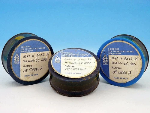
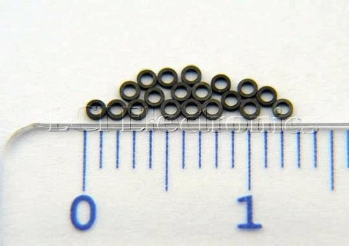
The cores came from DDR production stock, still in their original packaging. They are small, uniform, and obviously meant for a memory array rather than a one off experiment. Before I commit to a large weave, I need to know whether they still switch reliably, what current and pulse width they want, and how much crosstalk I should expect when several sit on the same drive lines.
Core memory is well documented in the literature. The magnetic core memory article is a useful refresher on drive, sense and inhibit lines. For rope style read only storage in the Apollo era, core rope memory and NASA’s summaries of the Apollo guidance computer put the engineering in context. None of that replaces measuring my own parts, but it sets expectations for polarity, half select currents, and the destructive read behaviour I will have to design around later.
Phase 1: Magnetic core memory testing
The first phase is deliberately modest. I want a single verified non-volatile bit, then a tiny array, with numbers I trust well enough to simulate the beacon storage in phase 2.
I will start with visual inspection and sorting, then a single bit fixture with hand wound drive and sense windings, current limited supplies, and repeatable pulse timing. The first numbers I want are switching threshold, minimum pulse width, and sense amplitude versus drive current. Those are planned measurements, not results yet. Once one bit is trustworthy, I will exercise destructive read and rewrite with the core cold and powered down between checks, then grow toward a small array (likely 8 or 16 bits first) to learn addressing, inhibit behaviour, and wiring discipline.
For instrumentation I plan to use an ESP32 as the pulse generator and sense front end, with timing-critical captures on a Sipeed SLogic32U3 logic analyser I have already purchased. Optional ADC modules on that platform would let me watch analogue tails on the sense line while I sweep drive current. Bench results are still pending; I have not yet published waveforms from these cores.
Community builds such as the Magnetic Core Memory shield and various university replica projects prove the idea is still approachable at hobby scale. I am not copying those boards directly, but they are helpful references for driver topology and the amount of frustration a hand wired plane can absorb.
Phase 2: CW integration
Phase 2 asks a specific question: can a magnetic memory module hold a short CW message that survives power loss, be read out under microcontroller control, and reach a transmitter without pretending the ferrite array is the radio?
The architecture I have in mind separates concerns cleanly:
Ferrite memory module → ESP32 → Wi-Fi → POTACAT on Raspberry Pi → USB CAT → QRP Labs QMXThe Raspberry Pi and the QRP Labs QMX live in the existing shack stack. They are not part of the magnetic memory sculpture. The ESP32 sits with the memory plane as a dedicated reader and network bridge. On the Pi, POTACAT already knows how to drive a QMX over serial CAT; I plan to run the desktop app there and use its remote interfaces for supervision, while the ferrite module remains a separate message store that companion logic can query. Nothing in that chain should key the transmitter on its own.
Destructive read cannot be avoided with core memory. The beacon workflow therefore looks like: read the message into RAM on the ESP32, immediately rewrite the cores from a shadow copy, then hand text or channel parameters to the Pi layer. If read fails, the system should fail silent on air rather than repeat garbage.
Remote control and safety need the same respect as any automated transmitter. I will keep manual oversight on the QMX, enforce a hard mute unless an operator arm flag is set, and never rely on Wi-Fi alone as an interlock. Maidenhead grid and callsign fields in configuration will use placeholders such as [LOCATOR] and [CALLSIGN] in examples so nothing on CVSS.IO ties the project to a particular station or location.
Phase 3: Functional art
If phases 1 and 2 teach me the electrical truth of these cores, phase 3 is where that truth becomes visible. The leading concept is a Smith chart inspired memory sculpture: rings of ferrite arranged like impedance contours, with real drive and sense wiring following the geometry instead of a decorative overlay.
The design rule is strict: every visible ferrite is a functioning memory element, and every visible wire carries current for a reason. Anything that fails that test gets redesigned or removed. The Smith chart is a guide for layout and for the radio story, not a finished mechanical drawing.
Visual references sit beside the RF theory rather than replacing it. The geodesic radomes at Menwith Hill and similar sites suggest scale and repetition without dictating dimensions. Fibonacci spirals and classic machines such as the IBM 1401 core plane remind me that these arrays were once shown off as industrial art. Phase 3 will borrow composition, not nostalgia for a single place or person.
What success looks like
Phase 1 succeeds when I can document switching parameters for my batch and show a small array holding data with the power removed. Phase 2 succeeds when a message stored in ferrite can be read back, restored, and reflected in a controlled CW transmission through the Pi and QMX chain. Phase 3 succeeds when someone can look at the sculpture, understand the Smith chart reference, and still trace a real electrical path through every core.
Until those milestones land, this page stays a log of intent. I will update it when the bench results deserve numbers, and when the first on air tests are responsible to run.
